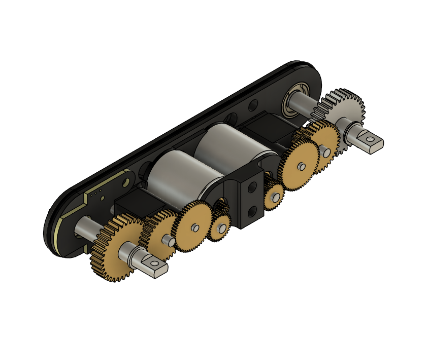
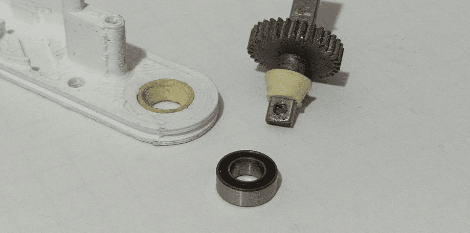
So as mentioned in the previous post I actually wanted to think a lil longer about the robot mechanics. So far I’ve been still revolving about the hobby servo approach - that is - using a small dc motor with a couple of gears and an encoder for feedback. Because this project started as a small weekend project, at first SG90 servos were used for legs (12 of them!)
Because of the heavy chassis I used, they broke down easily. Inside there were plastic (I assume nylon?) gears:
Without much of a hesitation I bought metal gear servos, MG90. They were a drop-in replacement for SG90, here pictured an even better version from Turnigy.
And of course another problem appeared. These servos seem to be rather simple with how they work: if the shaft is let’s say a bit to the left from the desired angle, we put power in the reverse direction to get closer to the desired point. And as much as it is great for “lightweight” stuff such as RC planes or boats, one servo having to quickly move an entire leg wasn’t the best idea. Those servos couldn’t reach the desired point, oscillating about it - which is called servo hunting. I had two options that time:
- switch to bigger MG996R servos
- create my own servos
Option b) seemed better because of the full control, and most importantly, custom gearbox. MG996 and similar are pretty slow compared to what I wanted to achieve, and would be good only for a prototype (and re-thinking this, they actually may not be that bad option…)
So I opened【FUSION 360】and started working on that. The first problem were the gears, and that problem still isn’t solved. Because the robot itself is going to be relatively small, the gears are going to be even smaller. We talk about gears of module as small as 0.2! So of course the first thing to do was to dismantle the available servos and see what I can reuse. MG90 turned out to have 4 almost identical gears of a rather uncommon 0.25 module, which combined either gave me a too fast or too slow output rotation. I found out that about 400RPM is desired here, because it’s possible to create a strong servo with such RPM but also it allows the leg to move fast. Like, actually fast! The robot when done properly could probably run like an actual headcrab. So, no MG90 gears. MG995 and similar also use different gears which didn’t prove to be useful, so I was left to do nothing but try to discover anything that could contain such gears on Aliexpress. Luckily, I was able to find most gears that were needed, besides the last two - which if possible to get, allowed for a compact and optimal design.

And so I’ve been trying to look for a manufacturer willing to make these gears out of metal, because SLA printed gears were rather models than gears. The project pretty much stalled at this point, because of school (learning for finals) and during the vacation I was occupied by iNap Malinka ™. This is where PCBWay helped and.. 3D printed gears out of metal!

Another problem appeared, who would have guessed. The gears were extremely rough. Probably stayed within +/- 0.2mm tolerance? Essentially I barely made a test servo by sanding each single tooth manually with a sandpaper, tapped the holes (it’s 304 stainless steel so it’s a pain to actually do anything with it) but I managed to create a working prototype.
Surely it had a lot of wiggle room, was loud and rough, but.. it worked. Even with a PID regulator! I remember I ran some tests back then to find the efficiency and it was acceptable, but I can’t find the results. Probably will make proper measurements later. What’s important for now, is that after the school I have time to freely experiment with new options.
Sooo let’s get back to the beginning, and reconsider some things? We surely want to create a custom servo. We have 3 motor types to decide from: a DC motor, a BLDC motor and a stepper motor. Steppers seem to fit since they’re pretty accurate even without feedback, but after checking out they’re still weak without any additional gearbox. And cannot really spin fast (or at least, I wasn’t find anything affordable and good). ((and adding feedback is still necessary so meh)).
BLDC motors were a no-go at first because of the sheer amount of amperes they take, stupidly expensive drivers (FOCs can be up to 200$! For ONE!!), but the bonus points for them is that they don’t require a big gearbox (simple 1:10 would be already sufficient) and they can offer LOTS of power. If you hadn’t seen Spot from Boston Dynamics running then go and watch it go, really. And that’s why I’m seriously considering to switch to BLDC motors, they’re essentially a standard in the RC world and going for DC motors is simply for making toys.
But!
So far the progress with DC servos is great and given the scale and everything, if done industrially, these robots could be cheap and simple to manufacture. That’s another point of view. And like.. everything is almost done, even gears are here (still untreated, but whatever). So I’m still considering them to be a great choice.
What I’m going to do then is to order a nice low-KV BLDC motor (so one that doesnt spin fast; aka a motor for drones), a big LiPo battery, and look for a universal FOC driver suitable for testing. I’m going to compare the two technologies and see what’s best for the project; furthermore, in the meantime I want to finish the TMC7300 code which also will allow to fully test out the DC motor option. I’ll also check if maybe something new dropped on Ali, maybe there actually are servos which I need?
Stay tuned!